Introduction
The EagleCore SOM carrier features Samtec Razor Beam LSHM Series connectors, which enable the connection of various AMD and Microchip SOM modules, such as the EagleCore PolarFire SoC, EagleCore ZU-Plus SoC etc. The EagleCore SOM carrier includes a High Pin Count (HPC) high-speed FMC connector that has maximum of 8 SERDES lines. This connector allows for the expansion of the board’s functionality by attaching custom or commercially available daughter boards. The EagleCore SOM Carrier offers several additional features designed to enhance functionality and flexibility to the user. The carrier board includes an SD card slot, which allows users to add additional memory for data storage or program storage, Power Management IC (PMIC), ensuring efficient and reliable power supply management, MIPI CSI-2 (Camera Serial Interface 2) connector, enabling efficient video and data transmission between the carrier board and compatible camera modules and much more.
Board Features
- 3 x CONN RCPT 120POS SMD GOLD
- FTDI FT2232H for FPGA and Host communication
- RJ45 JACK
- USB Type-C connector
- USB micro-B connector for OTG communication
- PCIe male header
- HDMI connector
- 12V DC power supply
- AMD and Microchip compatible JTAG Header for programming and debugging.
- FMC connector with a maximum of 154 IOs for user-defined purpose
- FMC HPC connector with a maximum of 8 x SERDES lines
- 2 x CAN header
- PMIC programming header with EN switch
- User-defined LEDs and switches
- MIPI connector for video and image processing
- 3 x SMA connectors
How to use EagleCore Carrier
The following sections describe how to use this module in detail.
Hardware Accessories Required
In addition to the module, you may require the accessories listed below for a convenient and expedited installation:
- 12 V DC Power Supply
- USB A to USB-C cable.
- Micro B USB cable
- A Xilinx Platform Cable USB II compatible JTAG programmer (Optional)
Boards Supported
- Numato Lab EagleCore ZU-Plus SoC SOM.
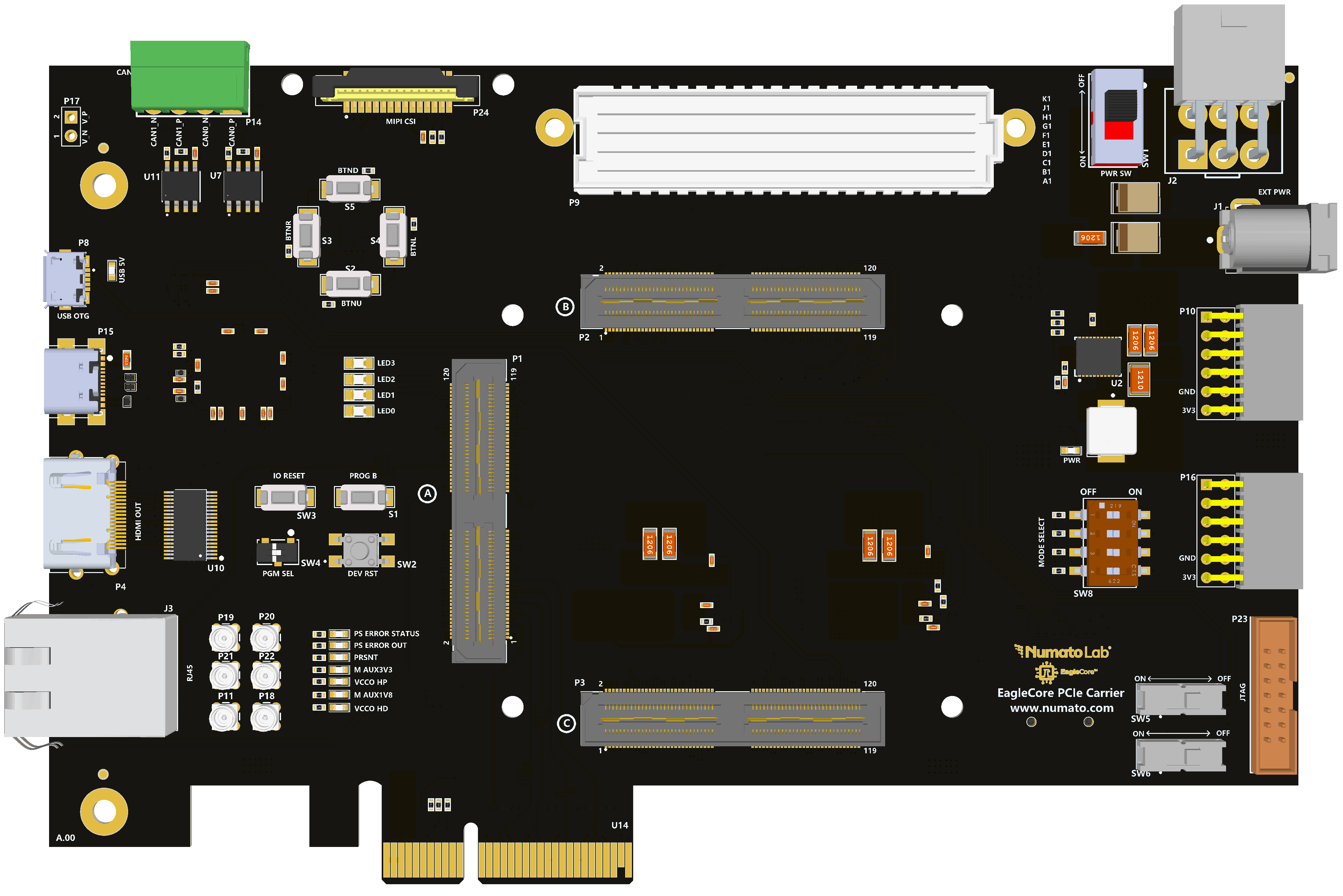
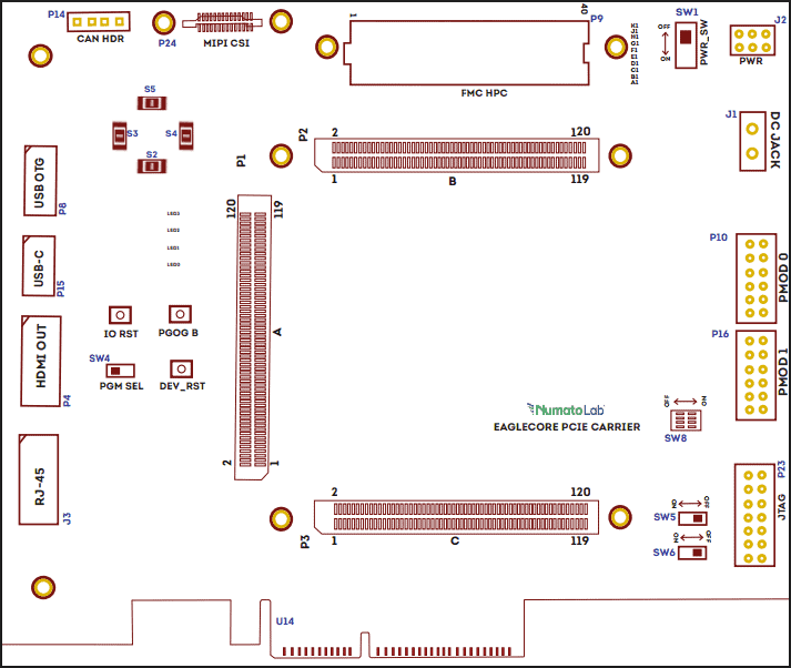
Connection Diagram
Note: The MicroSD Card slot and RTC Coin cell battery are kept below the carrier.
DC Power Supply
The EagleCore SOM Carrier is configured to use power from the DC power supply by connecting it to the
External DC Jack (J1). The external power supply should be in the range of +12V 5A.

Power Switch
The Power Switch (SW1)is used to switch on/off the board. Sliding it to ON to supply power from the External DC Jack to the board. Sliding it to OFF to power off the board.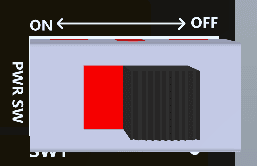
Power LED
The EagleCore SOM Carrier has a power LED (PWR) that will illuminate when the board receives sufficient power during startup.
Reset
The EagleCore SOM Carrier has a push button switch (SW2) for resetting the entire system. This pin is connected to the system reset pin of the FPGA.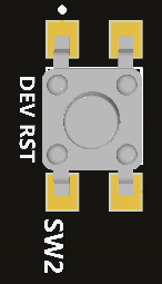
PROGB
The EagleCore SOM Carrier includes a dedicated switch (S1)for PROGB functionality, which is connected to the corresponding PROGB pin on the FPGA.
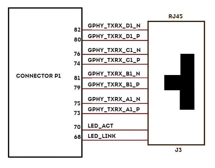
Gigabit Ethernet Port
The EagleCore SOM Carrier supports 1 Gigabit ethernet communication lanes (J3)which support 10/100/1000Mbps Ethernet interface. It also has an additional Activity and Link LED for providing visual indication for the user about the status of the ethernet. The Ethernet LINK LED indicates the presence of a network connection when illuminated, while the Gigabit Ethernet ACTIVITY LED signals active data transmission or reception over the network.
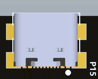
USB Interface
The onboard USB connector (P15) helps a PC/Linux/Mac computer to communicate with this module.
Use a USB type C cable to connect with a PC. This port will act as both JTAG and UART interface.
USB 2.0 OTG Connector
The EagleCore SOM Carrier provides a USB 2.0 OTG interface (P8) and can be accessed using a Micro-B
connector. USB OTG supports both Host, Device, and OTG modes based on the configuration made in the USB ID pin. An LED (USB_5V) is connected with the USB_5V as an indication of the presence of the VBUS in the USB pin.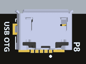
MicroSD Card
The EagleCore SOM Carrier supports a microSD card slot (P12), offering additional non-volatile 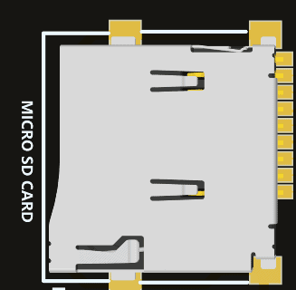
memory storage capacity. It operates in 3.3V and offers a compact and removable storage solution, making it ideal for storing data that exceeds the internal memory capacity of the FPGA. FPGAs can use microSD cards to store boot images or configuration data, which are loaded into the FPGA at startup.
Mode Selection DIP Switches
EagleCore SOM Carrier has DIP switches (SW8) for changing the boot configuration of the FPGA based on the required functionality. Users can utilize all four pins or only the necessary ones, leaving the remaining MODE pins unconnected.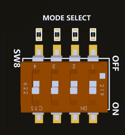
EagleCore ZU-Plus SOM
The boot configuration of the EagleCore ZU+ SOM will be based on the below configuration of switches:
| MODE3 | MODE2 | MODE1 | MODE0 | |
|---|---|---|---|---|
| JTAG | 0 | 0 | 0 | 0 |
| QSPI (32Bit) | 0 | 0 | 1 | 0 |
| SD Card(2.0) | 0 | 1 | 0 | 1 |
| EMMC (1.8V) | 0 | 1 | 1 | 0 |
RTC Coin Cell Holder
The EagleCore SOM Carrier has a Coin Cell Holder (BT1) to support 1.8V coin cell that will support 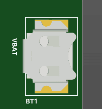
backup voltage for RTC when main power supply is off. RTC maintains accurate timekeeping through these battery-backup. The battery should be kept in the carrier board for providing voltage if the main power is off.
CAN Header
The EagleCore SOM Carrier has 2 CAN (P14)headers dedicated for CAN communication interfaces.

| Pin No. | Signal Name | Function |
|---|---|---|
| 1 | CANH | CAN0_P |
| 2 | CANL | CAN0_N |
| 3 | CANH | CAN1_P |
| 4 | CANL | CAN1_N |
PMIC Header
EagleCore SoC Carrier supports PMIC connector for programming the power section of the FPGA using I2C communication protocol (P10). It also includes a dedicated enable switch (SW3)to assist users in initially programming the PMIC.

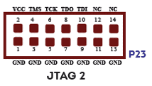
JTAG Header
EagleCore SOM Carrier supports standard JTAG Headers for programming and debugging purposes.
JTAG 2 – AMD (P23)
User Defined LEDs and Push Buttons
EagleCore SOM Carrier provides 4 user-defined LEDs.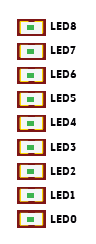
EagleCore SOM Carrier provides 4 Push buttons (S2, S3, S4, S5) for user-defined purposes.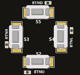
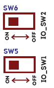
User Defined Switches
The EagleCore SOM Carrier has 2 dedicated switches (SW5 & SW6) for user defined purpose.
PGM_SEL switch
The EagleCore SOM Carrier supports both JTAG and FTDI programming for AMD FPGA boards. The configuration can be changes using PGM_SEL switch (SW4). By default, switch SW4 is in the ON position for JTAG programming configuration. When switched to the OFF position, it will configure the board for FTDI programming.

100 MHz Oscillator
The EagleCore SOM Carrier provides an additional 100 MHz LVDS oscillator for user defined purposes.
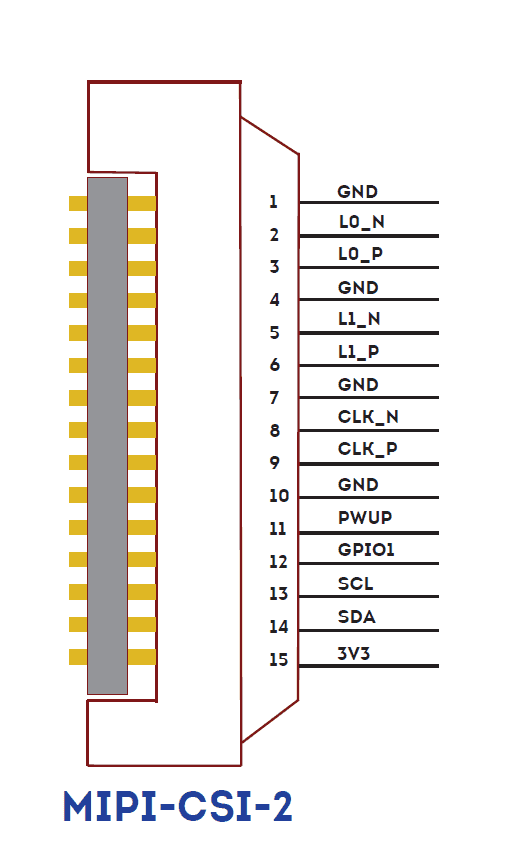
MIPI Header
The EagleCore SOM Carrier has a dedicated lines for MIPI CSI-2 connector (P24). MIPI CSI-2 is a standard interface for connecting cameras to FPGAs, enabling high-speed, efficient, and scalable image and video data transmission.
XADC Header
The EagleCore SOM Carrier have dedicated header (P17) for differential analog input.

SMA Connectors
The EagleCore SOM Carrier supports 3 SMA connectors for differential transceiver clocks. Users can 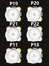
utilize this connector to meet additional transceiver clock requirements.
| Product No. | Signal Name |
|---|---|
| P11 | CLK_01_P |
| P18 | CLK_01_N |
| P19 | CLK_02_P |
| P20 | CLK_02_N |
| P21 | CLK_03_P |
| P22 | CLK_03_N |
FMC Header
EagleCore SOM Carrier features a high speed, high pin-count FMC connector which can be used to provide additional features and capabilities to it using custom or commercial-off-the-shelf daughter boards. Apart from IOs, 8 GTX lanes are available via FMC connector for custom purposes.
FMC BANKS A TO E
| A | FMC Pin Name | B | FMC Pin Name | C | FMC Pin Name | D | FMC Pin Name | E | FMC Pin Name |
|---|---|---|---|---|---|---|---|---|---|
| A1 | GND | B1 | GND | C1 | GND | D1 | PG_C2M | E1 | GND |
| A2 | FMC_DP1_M2C_P | B2 | GND | C2 | FMC_DP0_C2M_P | D2 | GND | E2 | FMC_HA01_CC_P |
| A3 | FMC_DP1_M2C_N | B3 | GND | C3 | FMC_DP0_C2M_N | D3 | GND | E3 | FMC_HA01_CC_N |
| A4 | GND | B4 | NC | C4 | GND | D4 | FMC_GBTCLK0_M2C_P | E4 | GND |
| A5 | GND | B5 | NC | C5 | GND | D5 | FMC_GBTCLK0_M2C_N | E5 | GND |
| A6 | FMC_DP2_M2C_P | B6 | GND | C6 | FMC_DP0_M2C_P | D6 | GND | E6 | FMC_HA05_P |
| A7 | FMC_DP2_M2C_N | B7 | GND | C7 | FMC_DP0_M2C_N | D7 | GND | E7 | FMC_HA05_N |
| A8 | GND | B8 | NC | C8 | GND | D8 | FMC_LA01_CC_P | E8 | GND |
| A9 | GND | B9 | NC | C9 | GND | D9 | FMC_LA01_CC_N | E9 | FMC_HA09_P |
| A10 | FMC_DP3_M2C_P | B10 | GND | C10 | FMC_LA06_P | D10 | GND | E10 | FMC_HA09_N |
| A11 | FMC_DP3_M2C_N | B11 | GND | C11 | FMC_LA06_N | D11 | FMC_LA05_P | E11 | GND |
| A12 | GND | B12 | NC | C12 | GND | D12 | FMC_LA05_N | E12 | FMC_HA13_P |
| A13 | GND | B13 | NC | C13 | GND | D13 | GND | E13 | FMC_HA13_N |
| A14 | NC | B14 | GND | C14 | FMC_LA10_P | D14 | FMC_LA09_P | E14 | GND |
| A15 | NC | B15 | GND | C15 | FMC_LA10_N | D15 | FMC_LA09_N | E15 | FMC_HA16_P |
| A16 | GND | B16 | NC | C16 | GND | D16 | GND | E16 | FMC_HA16_N |
| A17 | GND | B17 | NC | C17 | GND | D17 | FMC_LA13_P | E17 | GND |
| A18 | NC | B18 | GND | C18 | FMC_LA14_P | D18 | FMC_LA13_N | E18 | FMC_HA20_P |
| A19 | NC | B19 | GND | C19 | FMC_LA14_N | D19 | GND | E19 | FMC_HA20_N |
| A20 | GND | B20 | NC | C20 | GND | D20 | FMC_LA17_CC_P | E20 | GND |
| A21 | GND | B21 | NC | C21 | GND | D21 | FMC_LA17_CC_N | E21 | NC |
| A22 | FMC_DP1_C2M_P | B22 | GND | C22 | FMC_LA18_CC_P | D22 | GND | E22 | NC |
| A23 | FMC_DP1_C2M_N | B23 | GND | C23 | FMC_LA18_CC_N | D23 | FMC_LA23_P | E23 | GND |
| A24 | GND | B24 | NC | C24 | GND | D24 | FMC_LA23_N | E24 | NC |
| A25 | GND | B25 | NC | C25 | GND | D25 | GND | E25 | NC |
| A26 | FMC_DP2_C2M_P | B26 | GND | C26 | FMC_LA27_P | D26 | FMC_LA26_P | E26 | GND |
| A27 | FMC_DP2_C2M_N | B27 | GND | C27 | FMC_LA27_N | D27 | FMC_LA26_N | E27 | NC |
| A28 | GND | B28 | NC | C28 | GND | D28 | GND | E28 | NC |
| A29 | GND | B29 | NC | C29 | GND | D29 | NC | E29 | GND |
| A30 | FMC_DP3_C2M_P | B30 | GND | C30 | SCL_FMC | D30 | NC | E30 | NC |
| A31 | FMC_DP3_C2M_N | B31 | GND | C31 | SDA_FMC | D31 | NC | E31 | NC |
| A32 | GND | B32 | NC | C32 | GND | D32 | 3V3AUX | E32 | GND |
| A33 | GND | B33 | NC | C33 | GND | D33 | NC | E33 | NC |
| A34 | NC | B34 | GND | C34 | GND | D34 | NC | E34 | NC |
| A35 | NC | B35 | GND | C35 | P12V0 | D35 | P3V3 | E35 | GND |
| A36 | GND | B36 | NC | C36 | GND | D36 | P3V3 | E36 | NC |
| A37 | GND | B37 | NC | C37 | P12V0 | D37 | GND | E37 | NC |
| A38 | NC | B38 | GND | C38 | GND | D38 | P3V3 | E38 | GND |
| A39 | NC | B39 | GND | C39 | P3V3 | D39 | GND | E39 | VADJ |
| A40 | GND | B40 | NC | C40 | GND | D40 | P3V3 | E40 | GND |
FMC BANKS G TO K
| F | FMC Pin Name | G | FMC Pin Name | H | FMC Pin Name | J | FMC Pin Name | K | FMC Pin Name |
|---|---|---|---|---|---|---|---|---|---|
| F1 | PG_M2C | G1 | GND | H1 | NC | J1 | GND | K1 | NC |
| F2 | GND | G2 | NC | H2 | PRSNT_M2C_L | J2 | NC | K2 | GND |
| F3 | GND | G3 | NC | H3 | GND | J3 | NC | K3 | GND |
| F4 | FMC_HA00_CC_P | G4 | GND | H4 | NC | J4 | GND | K4 | NC |
| F5 | FMC_HA00_CC_N | G5 | GND | H5 | NC | J5 | GND | K5 | NC |
| F6 | GND | G6 | FMC_LA00_CC_P | H6 | GND | J6 | FMC_HA03_P | K6 | GND |
| F7 | FMC_HA04_P | G7 | FMC_LA00_CC_N | H7 | FMC_LA02_P | J7 | FMC_HA03_N | K7 | FMC_HA02_P |
| F8 | FMC_HA04_N | G8 | GND | H8 | FMC_LA02_N | J8 | GND | K8 | FMC_HA02_N |
| F9 | GND | G9 | FMC_LA03_P | H9 | GND | J9 | FMC_HA07_P | K9 | GND |
| F10 | FMC_HA08_P | G10 | FMC_LA03_N | H10 | FMC_LA04_P | J10 | FMC_HA07_N | K10 | FMC_HA06_P |
| F11 | FMC_HA08_N | G11 | GND | H11 | FMC_LA04_N | J11 | GND | K11 | FMC_HA06_N |
| F12 | GND | G12 | FMC_LA08_P | H12 | GND | J12 | FMC_HA11_P | K12 | GND |
| F13 | FMC_HA12_P | G13 | FMC_LA08_N | H13 | FMC_LA07_P | J13 | FMC_HA11_N | K13 | FMC_HA10_P |
| F14 | FMC_HA12_N | G14 | GND | H14 | FMC_LA07_N | J14 | GND | K14 | FMC_HA10_N |
| F15 | GND | G15 | FMC_LA12_P | H15 | GND | J15 | FMC_HA14_P | K15 | GND |
| F16 | FMC_HA15_P | G16 | FMC_LA12_N | H16 | FMC_LA11_P | J16 | FMC_HA14_N | K16 | FMC_HA17_CC_P |
| F17 | FMC_HA15_N | G17 | GND | H17 | FMC_LA11_N | J17 | GND | K17 | FMC_HA17_CC_N |
| F18 | GND | G18 | FMC_LA16_P | H18 | GND | J18 | FMC_HA18_P | K18 | GND |
| F19 | FMC_HA19_P | G19 | FMC_LA16_N | H19 | FMC_LA15_P | J19 | FMC_HA18_N | K19 | FMC_HA21_P |
| F20 | FMC_HA19_N | G20 | GND | H20 | FMC_LA15_N | J20 | GND | K20 | FMC_HA21_N |
| F21 | GND | G21 | FMC_LA20_P | H21 | GND | J21 | FMC_HA22_P | K21 | GND |
| F22 | NC | G22 | FMC_LA20_N | H22 | FMC_LA19_P | J22 | FMC_HA22_N | K22 | NC |
| F23 | NC | G23 | GND | H23 | FMC_LA19_N | J23 | GND | K23 | NC |
| F24 | GND | G24 | FMC_LA22_P | H24 | GND | J24 | NC | K24 | GND |
| F25 | NC | G25 | FMC_LA22_N | H25 | FMC_LA21_P | J25 | NC | K25 | NC |
| F26 | NC | G26 | GND | H26 | FMC_LA21_N | J26 | GND | K26 | NC |
| F27 | GND | G27 | FMC_LA25_P | H27 | GND | J27 | NC | K27 | GND |
| F28 | NC | G28 | FMC_LA25_N | H28 | FMC_LA24_P | J28 | NC | K28 | NC |
| F29 | NC | G29 | GND | H29 | FMC_LA24_N | J29 | GND | K29 | NC |
| F30 | GND | G30 | FMC_LA29_P | H30 | GND | J30 | NC | K30 | GND |
| F31 | NC | G31 | FMC_LA29_N | H31 | FMC_LA28_P | J31 | NC | K31 | NC |
| F32 | NC | G32 | GND | H32 | FMC_LA28_N | J32 | GND | K32 | NC |
| F33 | GND | G33 | FMC_LA31_P | H33 | GND | J33 | NC | K33 | GND |
| F34 | NC | G34 | FMC_LA31_N | H34 | FMC_LA30_P | J34 | NC | K34 | NC |
| F35 | NC | G35 | GND | H35 | FMC_LA30_N | J35 | GND | K35 | NC |
| F36 | GND | G36 | NC | H36 | GND | J36 | NC | K36 | GND |
| F37 | NC | G37 | NC | H37 | NC | J37 | NC | K37 | NC |
| F38 | NC | G38 | GND | H38 | NC | J38 | GND | K38 | NC |
| F39 | GND | G39 | VADJ | H39 | GND | J39 | VIO_B_M2C | K39 | GND |
| F40 | VADJ | G40 | GND | H40 | VADJ | J40 | GND | K40 | VIO_B_M2C |
FMC Technical Specifications
| Parameter | Value | Unit |
|---|---|---|
| Power supply voltage | 12 | V |
| Number of positions | 400 | |
| Number of rows | 10 | |
| Height above the board | 6.55 | mm |
| Pitch | 1.27 | mm |
| Number of connectors | 1 | |
| FMC connector | ASP-134486-01 |
FMC Present LED
The EagleCore SOM Carrier has a dedicated pin for the FMC present signal, which is connected to LED (D5). This LED serves as an indicator for the user to verify that the FMC Mezzanine Module is inserted properly. If the FMC is properly inserted, the LED will illuminate.
SOM Connector Header
Connector P1
| Pin No. | Signal Name | Pin Name | Pin No. | Signal Name | Pin Name |
|---|---|---|---|---|---|
| 1 | VDD1V8 | M_AUX1V8 | 2 | VCC3V3 | M_AUX3V3 |
| 3 | VDD1V8 | M_AUX1V8 | 4 | VCC3V3 | M_AUX3V3 |
| 5 | GND | Ground | 6 | GND | Ground |
| 7 | CLK0_P | PCIe_REFCLK_P | 8 | CLK1_P | CLK_01_P |
| 9 | CLK0_N | PCIe_REFCLK_N | 10 | CLK1_N | CLK_01_N |
| 11 | GND | Ground | 12 | GND | Ground |
| 13 | RX0_P | PCIe_RX0_P | 14 | TX0_P | PCIe_TX0_P |
| 15 | RX0_N | PCIe_RX0_N | 16 | TX0_N | PCIe_TX0_N |
| 17 | GND | Ground | 18 | GND | Ground |
| 19 | RX1_P | PCIe_RX1_P | 20 | TX1_P | PCIe_TX1_P |
| 21 | RX1_N | PCIe_RX1_R | 22 | TX1_N | PCIe_TX1_N |
| 23 | GND | Ground | 24 | GND | Ground |
| 25 | RX2_P | PCIe_RX2_P | 26 | TX2_P | PCIe_TX2_P |
| 27 | RX2_N | PCIe_RX2_N | 28 | TX2_N | PCIe_TX2_N |
| 29 | GND | Ground | 30 | GND | Ground |
| 31 | RX3_P | PCIe_RX3_P | 32 | TX3_P | PCIe_TX3_P |
| 33 | RX3_N | PCIe_RX3_N | 34 | RX3_N | PCIe_TX3_N |
| 35 | GND | Ground | 36 | GND | Ground |
| 37 | CLK2_P | CLK_02_P | 38 | CLK3_P | CLK_03_P |
| 39 | CLK2_N | CLK_02_N | 40 | CLK3_N | CLK_03_N |
| 41 | GND | Ground | 42 | GND | Ground |
| 43 | RX4_P | FMC_DP0_M2C_P | 44 | TX4_P | FMC_DP0_C2M_P |
| 45 | RX4_N | FMC_DP0_M2C_N | 46 | TX4_N | FMC_DP0_C2M_N |
| 47 | GND | Ground | 48 | GND | Ground |
| 49 | RX5_P | FMC_DP1_M2C_P | 50 | TX5_P | FMC_DP1_C2M_P |
| 51 | RX5_N | FMC_DP1_M2C_N | 52 | TX5_N | FMC_DP1_C2M_N |
| 53 | GND | Ground | 54 | GND | Ground |
| 55 | RX6_P | FMC_DP2_M2C_P | 56 | TX6_P | FMC_DP2_C2M_P |
| 57 | RX6_N | FMC_DP2_M2C_N | 58 | TX6_N | FMC_DP2_C2M_N |
| 59 | GND | Ground | 60 | GND | Ground |
| 61 | RX7_P | FMC_DP3_M2C_P | 62 | TX7_P | FMC_DP3_C2M_P |
| 63 | RX7_N | FMC_DP3_M2C_N | 64 | TX7_N | FMC_DP3_C2M_N |
| 65 | GND | Ground | 66 | GND | Ground |
| 67 | CLK4_P | FMC_GBTCLK0_M2C_P | 68 | LED/LINK | LED/Link |
| 69 | CLK4_N | FMC_GBTCLK0_M2C_N | 70 | LED/ACT | LED1/Activity |
| 71 | GND | Ground | 72 | GND | Ground |
| 73 | GPHY_A1_P | GPHY_TXRX_A1_P | 74 | GPHY_C1_P | GPHY_TXRX_A0_P |
| 75 | GPHY_A1_N | GPHY_TXRX_A1_N | 76 | GPHY_C1_N | GPHY_TXRX_A0_N |
| 77 | GND | Ground | 78 | GND | Ground |
| 79 | GPHY_B1_P | GPHY_TXRX_B1_P | 80 | GPHY_D1_P | GPHY_TXRX_B0_P |
| 81 | GPHY_B1_N | GPHY_TXRX_B1_N | 82 | GPHY_D1_N | GPHY_TXRX_B0_N |
| 83 | GND | Ground | 84 | GND | Ground |
| 85 | CAN0_TX | CAN0 _TX | 86 | CAN1_TX | GPHY_TXRX_C0_P |
| 87 | CAN0_RX | CAN0_RX | 88 | CAN1_RX | GPHY_TXRX_C0_N |
| 89 | GND | Ground | 90 | GND | Ground |
| 91 | PS_ERROR_STATUS | PS_ERROR_STATUS | 92 | V_P | GPHY_TXRX_D0_P |
| 93 | PS_ERROR_OUT | PS_ERROR_OUT | 94 | V_N | GPHY_TXRX_D0_N |
| 95 | VBAT | VBAT | 96 | PROG_B | LED0/Link |
| 97 | MIO | PCIe _PERST# | 98 | PRSNT_L | LED0/Activity |
| 99 | GND | Ground | 100 | GND | Ground |
| 101 | IO0_P | FMC_LA28_P | 102 | IO1_P | FMC_LA29_P |
| 103 | IO0_N | FMC_LA28_N | 104 | IO1_N | FMC_LA29_N |
| 105 | IO2_P | FMC_LA30_P | 106 | IO3_P | FMC_LA31_P |
| 107 | IO2_N | FMC_LA30_N | 108 | IO3_N | FMC_LA31_N |
| 109 | GND | Ground | 110 | GND | Ground |
| 111 | IO4_P | SW0 | 112 | IO5_P | LED_0 |
| 113 | IO4_N | SW1 | 114 | IO5_N | LED_1 |
| 115 | IO6_P | SW2 | 116 | IO7_P | LED_2 |
| 117 | IO6_N | SW3 | 118 | IO7_N | LED_3 |
| 119 | GND | Ground | 120 | GND | Ground |
| GND | Ground | GND | Ground | ||
| GND | Ground | GND | Ground | ||
| GND | Ground | GND | Ground | ||
| GND | Ground | GND | Ground |
Connector P2
| Pin No. | Signal Name | Pin Name | Pin No. | Signal Name | Pin Name |
|---|---|---|---|---|---|
| 1 | 5V0 | 5P0 | 2 | 5V0 | 5P0 |
| 3 | 5V0 | 5P0 | 4 | 5V0 | 5P0 |
| 5 | 5V0 | 5P0 | 6 | 5V0 | 5P0 |
| 7 | GND | Ground | 8 | GND | Ground |
| 9 | GND | Ground | 10 | GND | Ground |
| 11 | VCC_IO | VCC_IO_HP | 12 | VCC_IO | M_AUX1V8 |
| 13 | VCC_IO | VCC_IO_HP | 14 | VCC_IO | M_AUX1V8 |
| 15 | GND | Ground | 16 | GND | Ground |
| 17 | IO0_P | FMC_LA00_CC_P | 18 | IO1_P | FMC_LA01_CC_P |
| 19 | IO0_N | FMC_LA00_CC_N | 20 | IO1_N | FMC_LA01_CC_N |
| 21 | IO2_P | FMC_LA02_P | 22 | IO3_P | FMC_LA03_P |
| 23 | IO2_N | FMC_LA02_N | 24 | IO3_N | FMC_LA03_N |
| 25 | GND | Ground | 26 | GND | Ground |
| 27 | IO4_P | FMC_LA04_P | 28 | IO5_P | FMC_LA05_P |
| 29 | IO4_N | FMC_LA04_N | 30 | IO5_N | FMC_LA05_N |
| 31 | IO6_P | FMC_LA06_P | 32 | IO7_P | FMC_LA07_P |
| 33 | IO6_N | FMC_LA06_N | 34 | IO7_N | FMC_LA07_N |
| 35 | GND | Ground | 36 | GND | Ground |
| 37 | IO8_P | FMC_LA08_P | 38 | IO9_P | FMC_LA09_P |
| 39 | IO8_N | FMC_LA08_N | 40 | IO9_N | FMC_LA09_N |
| 41 | IO10_P | FMC_LA10_P | 42 | IO11_P | FMC_LA11_P |
| 43 | IO10_N | FMC_LA10_N | 44 | IO11_N | FMC_LA11_N |
| 45 | GND | Ground | 46 | GND | Ground |
| 47 | IO12_P | FMC_LA12_P | 48 | IO13_P | FMC_LA13_P |
| 49 | IO12_N | FMC_LA12_N | 50 | IO13_N | FMC_LA13_N |
| 51 | IO14_P | MIPI_L0_P | 52 | IO15_P | FMC_LA14_P |
| 53 | IO14_N | MIPI_L0_N | 54 | IO15_N | FMC_LA14_N |
| 55 | GND | Ground | 56 | GND | Ground |
| 57 | IO16_P | MIPI_L1_P | 58 | IO17_P | FMC_LA15_P |
| 59 | IO16_N | MIPI_L1_N | 60 | IO17_N | FMC_LA15_N |
| 61 | IO18_P | MIPI_CLK_P | 62 | IO19__P | HDMI_TX_CLK_P |
| 63 | IO18_N | MIPI_CLK_N | 64 | IO19_N | HDMI_TX_CLK_N |
| 65 | GND | Ground | 66 | GND | Ground |
| 67 | IO20_P | HDMI_TX0_P | 68 | IO21_P | HDMI_TX2_P |
| 69 | IO20_N | HDMI_TX0_N | 70 | IO21_N | HDMI_TX2_N |
| 71 | IO22_P | HDMI_TX1_P | 72 | IO23_P | FMC_HA01_CC_P |
| 73 | IO22_N | HDMI_TX1_N | 74 | IO23_N | FMC_HA01_CC_N |
| 75 | GND | Ground | 76 | GND | Ground |
| 77 | IO24_P | FMC_HA00_CC_P | 78 | IO25_P | FMC_HA03_P |
| 79 | IO24_N | FMC_HA00_CC_N | 80 | IO25_N | FMC_HA03_N |
| 81 | IO26_P | FMC_HA02_P | 82 | IO27_P | FMC_HA05_P |
| 83 | IO26_N | FMC_HA02_N | 84 | IO27_N | FMC_HA05_N |
| 85 | GND | Ground | 86 | GND | Ground |
| 87 | IO28_P | FMC_HA04_P | 88 | IO29_P | FMC_HA07_P |
| 89 | IO28_N | FMC_HA04_N | 90 | IO29_N | FMC_HA07_N |
| 91 | IO30_P | FMC_HA06_P | 92 | IO31_P | FMC_HA09_P |
| 93 | IO30_N | FMC_HA06_N | 94 | IO31_N | FMC_HA09_N |
| 95 | GND | Ground | 96 | GND | Ground |
| 97 | IO32_P | FMC_HA08_P | 98 | IO33_P | FMC_HA11_P |
| 99 | IO32_N | FMC_HA08_N | 100 | IO33_N | FMC_HA11_N |
| 101 | IO32_P | FMC_HA10_P | 102 | IO35_P | FMC_HA13_P |
| 103 | IO32_N | FMC_HA10_N | 104 | IO35_N | FMC_HA13_N |
| 105 | GND | Ground | 106 | GND | Ground |
| 107 | IO36_P | FMC_HA12_P | 108 | IO37_P | FMC_HA14_P |
| 109 | IO36_N | FMC_HA12_N | 110 | IO37_N | FMC_HA14_N |
| 111 | SD_CLK | SD_CLK | 112 | SD_DATA0 | SD_DATA0 |
| 113 | SD_CMD | SD_CMD | 114 | SD_DATA1 | SD_DATA1 |
| 115 | UART_RXD | UART_RXD | 116 | SD_DATA2 | SD_DATA2 |
| 117 | UART_RXD | UART_RXD | 118 | SD_DATA3 | SD_DATA3 |
| 119 | GND | Ground | 120 | GND | Ground |
| GND | Ground | GND | Ground | ||
| GND | Ground | GND | Ground | ||
| GND | Ground | GND | Ground | ||
| GND | Ground | GND | Ground |
Connector P3
| Pin No. | Signal Name | Pin Name | Pin No. | Signal Name | Pin Name |
|---|---|---|---|---|---|
| 1 | 5V0 | 5P0 | 2 | 5V0 | 5P0 |
| 3 | 5V0 | 5P0 | 4 | 5V0 | 5P0 |
| 5 | 5V0 | 5P0 | 6 | 5V0 | 5P0 |
| 7 | GND | Ground | 8 | GND | Ground |
| 9 | GND | Ground | 10 | GND | Ground |
| 11 | VDD3V3 | M_AUX3V3 | 12 | VCC_IO | VCC_IO_HD |
| 13 | VDD3V3 | M_AUX3V3 | 14 | VCC_IO | VCC_IO_HD |
| 15 | GND | Ground | 16 | GND | Ground |
| 17 | IO0_P | FMC_LA16_P | 18 | IO1_P | FMC_LA17_CC_P |
| 19 | IO0_N | FMC_LA16_N | 20 | IO1_N | FMC_LA17_CC_N |
| 21 | IO2_P | FMC_LA18_P | 22 | IO3_P | FMC_LA19_P |
| 23 | IO2_N | FMC_LA18_N | 24 | IO3_N | FMC_LA19_N |
| 25 | GND | Ground | 26 | GND | Ground |
| 27 | IO4_P | FMC_LA20_P | 28 | IO5_P | FMC_LA21_P |
| 29 | IO4_N | FMC_LA20_N | 30 | IO5_N | FMC_LA21_N |
| 31 | IO6_P | FMC_LA22_P | 32 | IO7_P | FMC_LA23_P |
| 33 | IO6_N | FMC_LA22_N | 34 | IO7_N | FMC_LA23_N |
| 35 | GND | Ground | 36 | GND | Ground |
| 37 | IO8_P | FMC_LA24_P | 38 | IO9_P | FMC_LA25_P |
| 39 | IO8_N | FMC_LA24_N | 40 | IO9_N | FMC_LA25_N |
| 41 | IO10_P | FMC_LA26_P | 42 | IO11_P | FMC_LA27_P |
| 43 | IO10_N | FMC_LA26_N | 44 | IO11_N | FMC_LA27_N |
| 45 | GND | Ground | 46 | GND | Ground |
| 47 | IO12_P | MIPI_PWUP | 48 | IO13_P | HDMI_TX_CEC |
| 49 | IO12_N | MIPI_GPIO | 50 | IO13_N | HDMI_TX_HOT |
| 51 | IO14_P | MIPI_SCL | 52 | IO15_P | HDMI_TX_SCL |
| 53 | IO14_N | MIPI_SDA | 54 | IO15_N | HDMI_TX_SDA |
| 55 | GND | Ground | 56 | GND | Ground |
| 57 | IO16_P | CONN0_D1 | 58 | IO17_P | CONN0_D8 |
| 59 | IO16_N | CONN0_D2 | 60 | IO17_N | CONN0_D7 |
| 61 | IO18_P | CONN0_D3 | 62 | IO19_P | CONN0_D6 |
| 63 | IO18_N | CONN0_D4 | 64 | IO19_N | CONN0_D5 |
| 65 | GND | Ground | 66 | GND | Ground |
| 67 | IO20_P | CONN1_D1 | 68 | IO21_P | CONN1_D8 |
| 69 | IO20_N | CONN1_D2 | 70 | IO21_N | CONN1_D7 |
| 71 | IO22_P | CONN1_D3 | 72 | IO23_P | CONN1_D6 |
| 73 | IO22_N | CONN1_D4 | 74 | IO23_N | CONN1_D5 |
| 75 | GND | Ground | 76 | GND | Ground |
| 77 | IO24_P | SCL_FMC | 78 | IO25_P | SWITCH1 |
| 79 | IO24_N | SDA_FMC | 80 | IO25_N | SWITCH2 |
| 81 | IO26_P | FMC_HA16_P | 82 | IO27_P | FMC_HA15_P |
| 83 | IO26_N | FMC_HA16_N | 84 | IO27_N | FMC_HA15_N |
| 85 | GND | Ground | 86 | GND | Ground |
| 87 | IO28_P | FMC_HA18_P | 88 | IO29_P | FMC_HA17_CC_P |
| 89 | IO28_N | FMC_HA18_N | 90 | IO29_N | FMC_HA17_CC_N |
| 91 | IO30_P | FMC_HA20_P | 92 | IO31_P | FMC_HA19_P |
| 93 | IO30_N | FMC_HA20_N | 94 | IO31_N | FMC_HA19_N |
| 95 | GND | Ground | 96 | GND | Ground |
| 97 | IO32_P | FMC_HA22_P | 98 | IO33_P | FMC_HA21_P |
| 99 | IO32_N | FMC_HA22_N | 100 | IO33_N | FMC_HA21_N |
| 101 | GND | Ground | 102 | GND | Ground |
| 103 | MODE 0 | MODE 0 | 104 | MODE 2 | MODE 2 |
| 105 | MODE 1 | MODE 1 | 106 | MODE 3 | MODE 3 |
| 107 | USB_DN | OTG_D_N | 108 | USB_ID | OTG_USB_ID |
| 109 | USB_DP | OTG_D_P | 110 | USB_5V | OTG_USB_5V |
| 111 | JTAG_TDI | FPGA_TDI | 112 | JTAG_TDO | FPGA_TDO |
| 113 | JTAG_TMS | FPGA_TMS | 114 | JTAG_TCK | FPGA_TCK |
| 115 | IO_RESET | IO_RESET | 116 | DEV_RST | DEV_RST |
| 117 | PG_M2C | PG_GOOD | 118 | PG_C2M | PG_ALL |
| 119 | GND | Ground | 120 | GND | Ground |
| GND | Ground | GND | Ground | ||
| GND | Ground | GND | Ground | ||
| GND | Ground | GND | Ground | ||
| GND | Ground | GND | Ground |
Technical Specification
| Parameter | Value | Unit |
|---|---|---|
| Basic Specification | ||
| Power supply voltage | 12 | V |
| Number of Positions | 100 | |
| Number of Rows | 2 | |
| Height above Board | 8.84 | mm |
| Pitch | 0.50 | mm |
| Mated Stacking Heights | 5,8,11,14,16 | mm |
| CONN RCPT 120POS SMD GOLD | 3 |
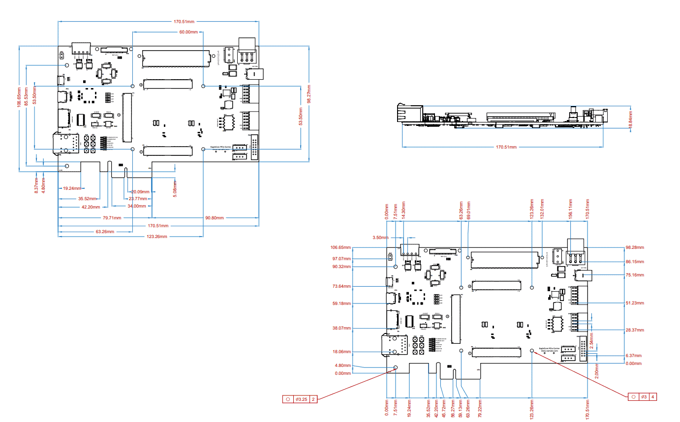
Physical Dimensions